
In the current validation example, we investigate wind pressure coefficient (Cp) of flat roof and walls with ASCE7-22 [1]. In the section 28.3 (Wind loads - main wind force resisting system) and Figure 28.3-1 (load case 1), there is a table which shows Cp value for different roof angle.
The Architectural Institute of Japan (AIJ) has presented a number of well-known benchmark scenarios of wind simulation.
The following article deals with "Case E - Building Complex in Actual Urban Area with Dense Concentration of Low-Rise Buildings in Niigata City".
In the following, the described scenario is simulated in RWIND& 2 and the results are compared with the simulated and experimental results by AIJ.

In the current validation example, we investigate wind pressure value for both general structural designs (Cp,10) and cladding or façade design (Cp,1) of rectangular plan buildings with EN 1991-1-4 [1]. There are three dimensional cases that we will explain more about if in the next part.
Das Architectural Institute of Japan (AIJ) hat eine Reihe an bekannten Benchmark-Szenarien für Windsimulation vorgestellt.
Der Nachfolgende Beitrag dreht sich dabei um den "Case A - high-rise building with a 2:1:1 shape".
Im Folgenden wird das beschriebene Szenario in RWIND2 nachgebildet und die Ergebnisse mit den simulierten und der experimentellen Resultate des AIJ verglichen.
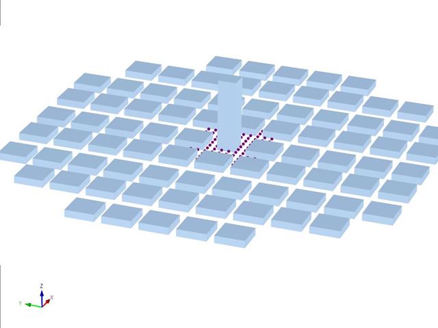
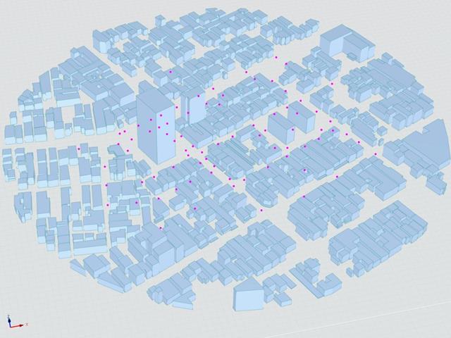
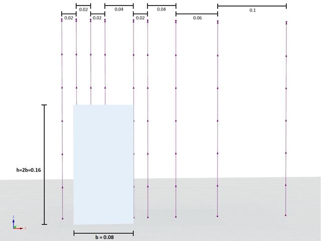
The Architectural Institute of Japan (AIJ) has presented a number of well-known benchmark scenarios of wind simulation.
The following article deals with "Case D - High-Rise Building Among City Blocks".
In the following, the described scenario is simulated in RWIND 2 and the results are compared with the simulated and experimental results by the AIJ.
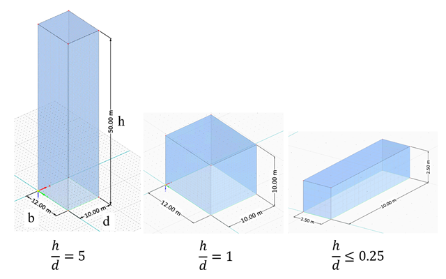
In the current validation example, we investigate wind force coefficient (Cf) of cube shapes with EN 1991-1-4 [1]. There are three dimensional cases that we will explain more about if in the next part.
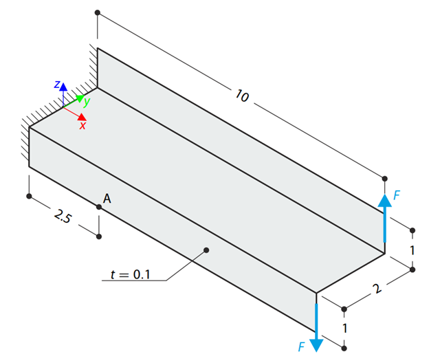
A Z-Section Cantilever is fully fixed at the end and loaded by a torque which, in the case of a shell model, is represented by a couple of shear forces. Determine the axial stress at point A (at mid-surface). The problem is defined according to The Standard NAFEMS Benchmarks.
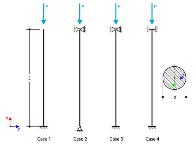
A strut with a circular cross-section is supported according to four basic cases of Euler buckling and subjected to pressure force. Determine the critical load.

A column is composed of a concrete section (rectangle 100/200) and a steel section (profile I 200). It is subjected to pressure force. Determine the critical load and corresponding load factor. The theoretical solution is based on the buckling of a simple beam. In this case, two regions have to be taken into account due to different moments of inertia and material properties.
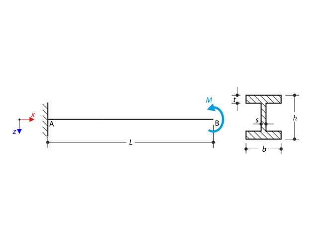
An I-profile cantilever is supported on the left end and loaded by torque. The aim of this example is to compare the fixed support with the fork support and to investigate the behavior of some representative quantities. Comparison is also made to the solution by means of plates. Small deformations are considered, and the self-weight is neglected. Determine the rotation in the midpoint of the cantilever, and in case of the member entity with warping, determine the values of the primary torsional moment, the secondary torsional moment, and the warping moment both on the left end (point A) and the right end (point B).
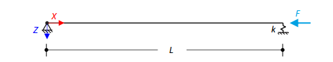
An axially loaded steel beam with a square cross-section is pinned at one end and spring-supported at the other. Two cases with different spring stiffnesses are considered. The verification example solves the calculation of the load factors of the beam in the image using the linear stability analysis.
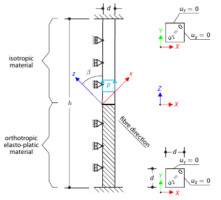
Determine the maximum deflection of a three-dimensional block fixed at both ends. The block is divided in the middle: the upper half is made of an elastic material and the lower part is made of timber - an elasto-plastic othotropic material with the yield surface described according to the Tsai-Wu plasticity theory. The block's middle plane is subjected to vertical pressure.